Bill Devlin
Adams County Master Gardener
 Recently I had the privilege to work with 17 freshmen students and 1 faculty member from Gettysburg College for the College's annual GIV (Gettysburg Is Volunteering) day.
The work that we undertook was to construct 6 eight-foot long benches for the skateboard facility in the Gettysburg Area Recreation Park.
When I was originally approached by Sharron Michels of Collaboration for Youth, United Way of Adams County, to come up with a design, and not readily coming up with plans from a brief internet search, I decided to do my own design. I had previously
put a seat railing completely around a 12' x 24' deck using my most comfortable deck chair as a pattern, so I repeated the approach.
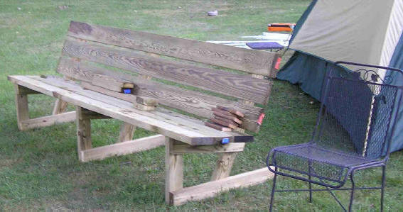
The following picture shows the completed prototype. This was put together by myself, a Naval Architect, Coast Guard Academy '56 and a Nuclear Engineer, Ray Schwartz, U.S. Military Academy, West Point, NY '67. Note that the pattern chair is to the
right. That's how I determined the angles and dimensions.
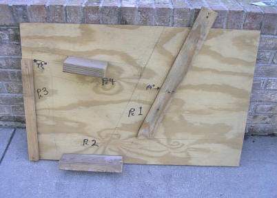
The following sketch shows the numbered pieces and the angular cuts that need to be made.
Piece one is the back support, its 36 inches long. The lower end is cut at a 67.5 degree angle, found by measuring the angle of the back of my comfortable lawn chair. Only one cut needs to be made for this piece. All these boards are pressure treated
wood for longevity. They may be painted after weathering for 60 days.
Piece two is the simplest of the pieces, being 32 inches long, with no angles other than the length cuts.
Piece three is 16.5 inches long, with the top cut at 7.5 degrees, the angle of the seat from the horizontal.
Piece four is the most complicated, 20.5 inches long with the front angle of 7.5 degrees and the rear angle at 14 degrees.
For an 8 foot bench, three supports are needed. These need to be exactly the same dimensions, a target easily achieved by the use of a jig. My jig is shown below, and I will loan it out if desired, email me at devlinw1@aol.com.
 Our prototype went together quite well with 180# men driving the screws in, however we added 2" x 2" cross braces on the back when a little give was detected. The braces go from the top of the middle support to the bottoms of the outer supports.
With the lighter 18 year olds, we found that we had to back out the screws and redrive them to get the friction necessary for rigidity. Going forward, I recommend that construction adhesive be applied as the joints are made up, and they be rigidly
clamped together before screwing pieces together.
When the 18 person GIV crew arrived at Gettysburg Area Community Park, we 'counted off' and every third member was appointed team coordinator. The following instructions were given and followed:
Brief training will be on safety, layout, how to use the jig that was built and used for the prototype. Also, the importance of squareness and accuracy in layout.
Work flow: Since we have so little time and so many people, we need a workflow that keeps everyone involved.
Step One, form 5 teams and designate leader. Layout boards side by side just as they appear on prototype, three seat boards and 3 back boards. Ends even or excess between types evenly distributed.
Step two, with a square, mark the lines that the seats and back will be screwed through. Note that the seat and back will be offset 1/12 inches. Note that they will be offset 1/12 inches as the supports will be offset that amount. For the left
support, facing the bench, the line on seat should be 8" in from the left end, the back 6 1/2" from the left (adjust for overage in the boards, the lines should be offset exactly 1 1/2 Inches.
Right side, seat 6 1/2" from right back 8" inches (again adjust for any board overage.
For the middle support, exactly bisect the length for centerline for seats; offset back 1 1/2" to left. We could use as many measuring tapes as possible, name labeled so they get back to their owners.
Step three predrill the holes, as drills become available. For the top screw in the top back board, keep 2" from edge, rest 1". This is to reduce chance of splitting the support boards. Predrilling is frosting on the cake as the screws can be driven
without predrilling if necessary, but screwing together will go faster if predrilled, so more people won't be standing around.
Step four, the critical path will go through the single support jig, so we will predrill one hole per corner assembly, two sets will allow the bench to get started and the third (middle support) can be installed later. This will get the teams working
faster with less dead time.
Step five, get the benches assembled with two end supports. Level each set as they are started. First Board is seat board at the rear of the bench, next step is lower back board. Level at this point. Spacers are used between seat board and back
board, and each subsequent back board, to insure esthetics. Keep watch that they are level as they are assembled.
Step six, install the middle support, keeping watch they are level.
Step seven, when all the rest is assembled, install the diagonal braces. Since these are small, predrilling is required to avoid splitting, also do not over drive as they will split.
Materials List
Fastenings.
- 1# per bench 2 ½" galvanized Phillips head deck screws
- Construction adhesive
Back
- 3 eight foot 5/4" x 6" pressure treated deck boards
Seat
- 3 eight foot 2" x 6" pressure treated boards
Supports
- 4 eight foot 2" x 4" pressure treated boards
Read other articles By Bill Devlin